The PIXELATOR MINI serves as the main hub in the PLINK control system. It can convert up to 16 Universes (32U in overdrive mode) of Art-Net, sACN, and ESP through 8 RJ45 ports. These ports transmit our proprietary protocol (PLINK DATA) up to 300m using a Cat6 cable to a PLINK INJECTOR (SPI Pixel Driver) or CVC4 (Auto-Adressing Constant Voltage LED Dimmer).

TABLE OF CONTENTS
PIXELATOR MINI
Revisions
Please check product serial number to understand the PIXELATOR MINI's revision:
- Revision v1.x - Serial number using the following hex code format: 0050C20XXXXX
- Revision v2.x - Serial number is a 7-digit numerical figure (e.g. 1234567)
Documentation & Firmware
Please find the latest documentation and firmware for the PIXELATOR MINI within the Dowload section of our website.
Overdrive Mode (Revision v2.x only)
The Universe capacity has been increased with Overdrive Mode, allowing for 4U per output. The Pixelators default will be 2U per port. It's important to consider that setting the output to a higher Universe count will decrease the maximum framerate. Users should be cautious of the maximum framerate achievable in each Overdrive Universe, depending on their lighting fixture. The maximum refresh rates per Universe per output are as follows:
- 1U = 100 fps
- 2U = 97 fps
- 3U = 65 fps
- 4U = 48 fps
SPI Protocols
The PIXELATOR MINI has a range of popular SPI Protocols preprogrammed within the firmware.
There are hundreds of SPI protocol varients, and this list is going to keep growing. To accommodate this growing range of SPI protocols the PIXELATOR MINI allows you to create a custom SPI protocol via the web interface. Please view our
Custom Protocol Creation Guide for further information.
Note: Not all SPI protocols are controllable with the PIXELATOR MINI, please see the Custom Protocol Creation Guide for the required SPI protocol criteria.
PLINK DATA
What is PLINK DATA?
In some installations, a maximum cable distance of 3m is not viable (see below). ENTTEC created a solution to this issue, PLINK DATA. PLINK DATA is a balanced signal, which means that the recommended a maximum cable distance is 300m. The PLINK DATA is transported via Cat6 cable.
Pixel data (SPI) is an unbalanced signal, resulting in the data degrading quickly, making it unusable after a few meters after the controller - we recommend a maximum cable distance of 3m when working with an unbalanced signal to ensure a reliable installation.Cat6 Cabling
PLINK DATA is sent out of a PIXELATOR MINI through its 8 rear RJ45 ports. ENTTEC recommends using a:
- Shielded Cat6 cable for PLink runs to reduce the chances of installations being impacted by EMI (Electro-Magnetic Interference). This isn’t crucial for all installations, however it’s another step to ensuring your installation goes as smoothly as possible. The shield layer and the drain wire (if your cable has one) should be connected to electrical earth separately to the data connections entering the device. This should never be attached to pin 7 (data GND - 0V).
- Independent Cat6 cable running from a single Pixelator Mini output to one PLink Injector. Splitting or joining Cat6 cable can lead to degraded performance or other electrical issues. The PLINK DATA only requires the use of 3 pins, the other 5 pins are unused.
| Function | RJ45 pin | Core Colour (terminated to TIA/EIA-568-B standard) |
| PLINK Data + | 1 | Orange White |
| PLINK Data - | 2 | Orange |
| N/C | 3 | Green White |
| N/C | 4 | Blue |
| N/C | 5 | Blue White |
| N/C | 6 | Green |
| 0V | 7 | Brown White |
| N/C | 8 | Brown |
PLINK INJECTOR
At the other end of the Cat 6 cable, the balanced PLink Data needs to be converted back to the unbalanced Pixel data (SPI). This is done by one of the following PLink Injector devices:
- 73544: 12-24v PLink Injector (designed for LED Pixel Voltage between 12-24v)
- 73546: 5v PLink Injector (designed for LED Pixel Voltage is 5v)
- 73924: IP66 PLink Injector (designed for outdoor use and for LED Pixel Voltage of 5v and voltages between 12-24v)
If your LED pixels require a higher voltage, please see our Octo Mk2.
The PLink injector is a small box which will need to be located within 3m cable distance of the Pixels. Please see our SPI cabling guide.


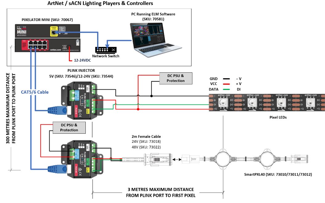
PLink Injector Wiring Diagram
Depending on the installation, there are two different ways that a PLink Injector can be wired:
- Backwards Fed Power: As seen for the first PLink Injector in the diagram below, this technique is similar to what is used on the ENTTEC Octo. As power in bidirectional (compare to data, which is unidirectional, only flows in one direction), the power supply can be placed on the PLink Injector output screw terminals and the power is backwards Fed.
- Power through-put: As seen for the second PLink Injector in the diagram below, the power supply is connected to the Power In port on the PLink, and the power is passed through the PLink Injector to the Pixels (in this case dots) on the PLink Injector output screw terminals. The PLink is limited to a 10Amp through-put, therefore if you are going to exceed 10Amps (50 watts at 5v, 120 watts at 12v, 240 watts at 24v etc), then you will need to use the Backwards Fed Power option below.
Important: The PLink is limited to a 10Amp through-put, therefore if you are going to exceed 10Amps (50 watts at 5v, 120 watts at 12v, 240 watts at 24v etc), then you will need to use the Backwards Fed Power option.
Note: Always ensure you appropriately fuse your installation and pay attention to the maximum current rating of your pixel strip or dots.
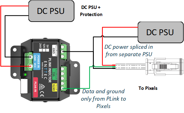
Controlling a Different Voltage
If you get caught out with the wrong voltage varient of the PLink, then it is possible to use the incorrect varient if you are unable to source the correct voltage vareient of the PLink.
As long as the PLink has the ability to support the pixel protocol of the higher/lower voltage pixel you intend to control, you can use your Plink to pass data and ground to the pixels, while you use a separate power supply of the pixel's required voltage to splice in *VCC & ground * to the pixels you are using.
This arrangement ensures that voltage is not passed directly from your pixel driver to the pixel strip - which ensures that neither the driver, not the pixel strip is damaged by over-voltage.